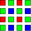
CCD and CMOS image sensors only see black and white. In
order for the camera to see color, small color filters are printed on top of the
image sensors. These filters are typically arranged in a Bayer pattern.

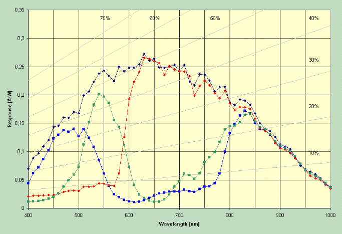
Below is the typical response curve for CCD and CMOS image
sensors that we found from a image sensor manufacturer. The top dark blue channel shows the quantum efficiency of an
unfiltered image sensor. The Red, Green and Blue traces show the
transmission response after the light passes through the mosaic color filter
over the image sensors.

When we convert a camera to see IR+Visible or IR-Only, the
majority of the infrared data will come in on the red channel.
Interestingly, the blue and green channels will see some infrared but will be
much lower than the red channel.
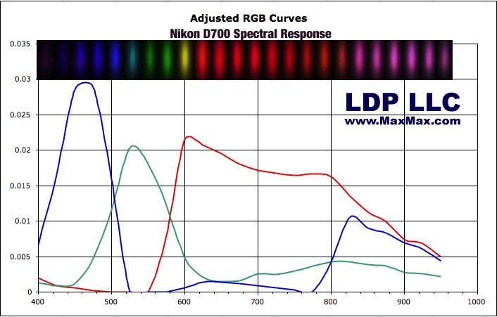
Below is a graph of a Nikon D700 spectral response curve that
we measured with our Ocean Optics spectrometer, monochromator and calibrated
light source. This measured curve is a bit different than the sensor
manufacturer curve which may be due to other processing that occurs in the
camera after you take a picture. The measured curve below is what you can
expect from a typical digital SLR camera

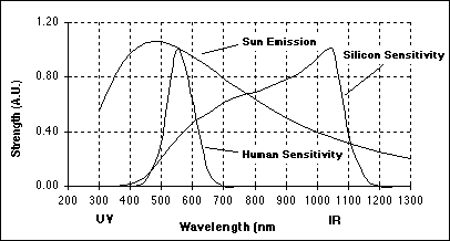
Below is shown a chart showing the typical sun emission
spectral curve, human sensitivity curve and silicon sensitivity curve.
CCD and CMOS sensors are based on silicon.

